Documentation Revision Date: 2025-03-06
Dataset Version: 1
Summary
The data include flight lines covering areas of interest to the ABoVE campaign over much of Alaska as well as the Yukon and Northwest Territories in northwestern Canada. These data will allow researchers to characterize ecosystem structure and function near the peak of the growing season. The AVIRIS-3 imaging spectroscopy dataset represents one part of a multi-sensor airborne sampling campaign conducted by eleven different aircraft teams for ABoVE.
Most files hold data for an entire flight line. In some cases, the flight line was divided into small scenes.
This dataset includes 358 data files. There are 357 files in ENVI image format (compressed in *.tar.gz format) and one GeoJSON providing the boundaries for the imagery captured for each flight line.
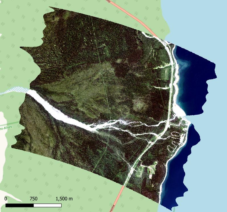
Figure 1. RGB image derived from L2 surface reflectance (R: 627 nm, G: 530 nm, B: 464 nm) for a portion of AVIRIS-3 flight AV320230716t204543 on July 16 2023. This scene includes Congdon Creek Territorial Park on the shore of Kluane Lake in western Yukon Territories, Canada (approximately -138.60 lon, 61.15 lat). Background map from OpenStreetMap (copyright OpenStreetMap contributors).
Citation
Miller, C.E., R.O. Green, and D.R. Thompson. 2025. ABoVE: AVIRIS-3 Imaging Spectroscopy for Alaska and Canada, 2023. ORNL DAAC, Oak Ridge, Tennessee, USA. https://doi.org/10.3334/ORNLDAAC/2388
Table of Contents
- Dataset Overview
- Data Characteristics
- Application and Derivation
- Quality Assessment
- Data Acquisition, Materials, and Methods
- Data Access
- References
Dataset Overview
This dataset includes L1B radiance and L2A surface reflectance imagery acquired by the Airborne Visible / Infrared Imaging Spectrometer-3 (AVIRIS-3) instrument over portions of Alaska and northwestern Canada in 2023. These data were collected for the Arctic-Boreal Vulnerability Experiment (ABoVE) project. NASA’s AVIRIS-3 is a spectral mapping system that measures reflected radiance at 7.4-nm intervals in the Visible to Shortwave Infrared (VSWIR) spectral range from 390-2500 nm. The AVIRIS-3 sensor has a 40 degree instantaneous field of view with 1234 pixels, providing altitude dependent ground sampling distances from 12 m to sub meter range. This dataset represents one part of a multi-sensor airborne sampling campaign conducted by eleven different aircraft teams for ABoVE.
The data include flight lines covering areas of interest to the ABoVE campaign over much of Alaska as well as the Yukon and Northwest Territories in northwestern Canada. These data will allow researchers to characterize ecosystem structure and function near the peak of the growing season. The AVIRIS-3 imaging spectroscopy dataset represents one part of a multi-sensor airborne sampling campaign conducted by eleven different aircraft teams for ABoVE. These data were specifically processed for the ABoVE project.
Most files hold data for an entire flight line. In some cases, the flight line was divided into small scenes. Future updates will provide data from separate scenes along each flight line. The scene-level files will be smaller in size and more easily managed by users.
Project: Arctic-Boreal Vulnerability Experiment
The Arctic-Boreal Vulnerability Experiment (ABoVE) is a NASA Terrestrial Ecology Program field campaign being conducted in Alaska and western Canada, for 8 to 10 years, starting in 2015. Research for ABoVE links field-based, process-level studies with geospatial data products derived from airborne and satellite sensors, providing a foundation for improving the analysis, and modeling capabilities needed to understand and predict ecosystem responses to, and societal implications of, climate change in the Arctic and Boreal regions.
Related Dataset:
Miller, C.E., R.O. Green, D.R. Thompson, A.K. Thorpe, M. Eastwood, I.B. Mccubbin, W. Olson-Duvall, M. Bernas, C.M. Sarture, S. Nolte, L.M. Rios, M.A. Hernandez, B.D. Bue, and S.R. Lundeen. 2024. ABoVE: AVIRIS-NG Imaging Spectroscopy for Alaska, Canada, and Iceland, 2017-2022, V3. ORNL DAAC, Oak Ridge, Tennessee, USA. https://doi.org/10.3334/ORNLDAAC/2362
Eckert, R., D.R. Thompson, A.M. Chlus, J.W. Chapman, M. Eastwood, M. Bernas, S. Geier, M. Helmlinger, D. Keymeulen, E. Liggett, S. Nadgauda, L.M. Rios, L.A. Shaw, W. Olson-Duvall, P.G. Brodrick, and R.O. Green. 2024. AVIRIS-3 L1B Calibrated Radiance, Facility Instrument Collection. ORNL DAAC, Oak Ridge, Tennessee, USA. https://doi.org/10.3334/ORNLDAAC/2356
- Eckert et al. (2024) is the Facility Instrument collection for AVIRIS-3. Its files may have been processed using different algorithms from those used for the ABoVE files included in this dataset.
Acknowledgements:
This study was funded by NASA's Arctic-Boreal Vulnerability Experiment (Grant number: NNX17AE44G).
Data Characteristics
Spatial Coverage: Alaska and western Canada within the ABoVE Domain
Spatial Resolution: Approximately 5 m
Temporal Coverage: 2023-07-15 to 2023-08-21
Temporal Resolution: One time
Study Area (All latitude and longitude are given in decimal degrees)
| Study Area | Northernmost Extent | Westernmost Extent | Easternmost Extent | Southernmost Extent |
|---|---|---|---|---|
| Alaska and Canada | 70.8021 | -166.4406 | -130.9689 | 55.1225 |
Data File Information
This dataset includes 358 data files. There are 357 files in ENVI image format (compressed in *.tar.gz format) and one GeoJSON providing the boundaries for the imagery captured for each flight line. There are 186 flight lines.
Level 1B (L1B) radiance and Level 2A (L2A) reflectance measurements are provided in separate gzip compressed TAR archives (*.tar.gz), and the data are provided in ENVI format with a binary data file and a header file in text format holding metadata.
Files for each flight line use a specific base filename prefix: AV3YYYYMMDDthhmmss, a flight line identifier which encodes the date and time of the flight. This prefix is used for the TAR filenames and the filenames for the data files contained therein.
- YYYY : Year of flight
- MM : Month of flight
- DD : Day of flight
- hh: UTC hour at start of flight
- mm: UTC minute at start of flight
- ss: UTC second at start of flight
The naming convention for the *.tar.gz files is <flight prefix>_<id>_<level>_<ver>.tar.gz, where
- <flight prefix> = flight line identifier, AV3YYYMMDDthhmmss (e.g., AV320230711t225833).
- <id> = a three digit flight scene (e.g., “000”), included for some but not all files.
- <level> = data level: “L1B_RDN_main” for Level 1B radiance; . "L2A_OE_main" for orthocorrected surface reflectance. The component “main” may be missing for some files.
- <ver> = unique seven character identifier of full heritage versioning.
Each tar.gz archive contains pairs of ENVI binary image files (no extension) and accompanying header files (*.hdr). The files within the tar.gz archive follow the same naming pattern as the archive, but the <product> designator is appended at the end of the filename:
<flight prefix>_<id>_<level>_<ver>_<product>, where
- <product> = “RDN_ORT” for L1B orthocorrected radiance, “GLT” for geometric lookup table, “IGM for input geometry, “LOC_ORT” for pixel location, “OBS_ORT” for observation parameters,
“RFL_ORT” for L2A orthocorrected reflectance, and “UNC_ORT” for reflectance uncertainty.
The binary ENVI files have no extension and are accompanied by a header file (*.hdr) of the same name in text format. The header files should remain in the same directory as the binary files for the data to be read properly. Header files provide spatial and spectral metadata related to the binary file, such as the number of lines, samples, channels, data ignore value, map projection, wavelengths in nm, and full-width at half-maximum (fwhm) values.
L1B Radiance Files
1) Calibrated and orthocorrected radiance data (RDN_ORT):
Level 1 calibrated radiance from AVIRIS-3 in 284 bands covering wavelengths between 390 nm to 2500 nm in approximately 7.4-nm intervals. Image cube dimensions = lines x samples x 284 bands.
Units: microwatts per centimeter squared per nanometer per steradian (µW cm-2 nm-1 sr-1) .
Radiance values are orthocorrected and projected into a UTM coordinate system noted in the map info line of the header file.
The header file records the spectral calibration (wavelength and full-width at half-maximum value) for every channel in the radiance data.
2) Geometric lookup table (GLT):
Provides information about which pixel in original instrument data occupies the output pixel in the final orthocorrected product.
Positive values indicate real data; negative values indicate nearest-neighbor filled data.
Two bands:
- Sample number in original instrument data
- Original line number
3) Input geometry file (IGM):
Contains UTM ground locations for each pixel in the corresponding unorthocorrected radiance image. See description line in header file for UTM zone.
Three bands:
- UTM easting (m)
- UTM northing (m)
- Estimated ground elevation at each pixel center (m)
4) Pixel location file (LOC_ORT):
Latitude/longitude pixel locations in WGS84 geographic coordinates for each orthocorrected pixel in the corresponding radiance image.
Three bands:
- WGS 84 longitude (decimal degrees)
- WGS 84 latitude (decimal degrees)
- Estimated ground elevation at each pixel center (m)
5) Observation parameters (OBS_ORT):
Observation parameter file that has been rendered using the GLT and matches the orthocorrected imagery.
Eleven bands:
- path length (sensor-to-ground in meters)
- to-sensor-azimuth (0 to 360 degrees clockwise from N)
- to-sensor-zenith (0 to 90 degrees from zenith)
- to-sun-azimuth (0 to 360 degrees clockwise from N)
- to-sun-zenith (0 to 90 degrees from zenith)
- solar phase (degrees between to-sensor and to-sun vectors in principal plane)
- slope (local surface slope as derived from DEM in degrees)
- aspect (local surface aspect 0 to 360 degrees clockwise from N)
- cosine i (apparent local illumination factor based on DEM slope and aspect and to-sun vector, -1 to 1)
- UTC time (decimal hours for mid-line pixels)
- Earth-sun distance (AU)
6) Processing information (*.yaml): A text file holding information about the algorithms used in processing to create these L1B data. It lists the input files and product generation execution parameters.
L2A Reflectance Files
1) Calibrated and orthocorrected surface reflectance (RFL_ORT):
Level 2 calibrated and BRDF-corrected reflectance in 284 bands covering wavelengths between 390 nm to 2500 nm in approximately 7.4-nm intervals. Image cube dimensions = lines x samples x 284 bands.
Units: apparent reflectance with valid values in 0.0 to 1.0 (Thompson et al., 2018; Thompson et al., 2019; Thompson et al., 2020).
Negative values indicate reflectance could not be computed.
The header file records the spectral calibration (wavelength and full-width at half-maximum value) for every channel and a bad band list (bbl).
2) Reflectance uncertainty (UNC_ORT):
Provides uncertainty estimates for the surface reflectance product. The header file records the spectral calibration (wavelength and full-width at half-maximum value) for every channel.
User Note: There are both L1 and L2 files for most flight lines.
These flight lines have L1B data only: AV320230717t214520, AV320230717t215508, AV320230717t223636, AV320230717t224712, AV320230728t195920, AV320230731t184217, AV320230731t210252, and AV320230821t173024.
These flight lines have L2A data only: AV320230717t195720, AV320230717t203638, AV320230801t203430, AV320230801t213027, AV320230805t182831, AV320230806t194829, AV320230807t005121,and AV320230812t211505.
Companion file: Information about file contents is also included in the companion file ABoVE_AV3_Data_Products_2023.txt.
Application and Derivation
Spectra measured by AVIRIS family instruments are used to identify, measure, and monitor constituents of the Earth's surface and atmosphere. Ecological applications include species composition, structure, and function; chlorophyll, leaf water, lignin, cellulose, pigment, and non-photosynthetic constituent content.
AVIRIS-3 was flown over the ABoVE domain (Figure 2) to characterize ecosystem structure and function near the height of the growing season during June - July of 2023.
Quality Assessment
All AVIRIS-3 data are processed at NASA’s Jet Propulsion Laboratory. Anomalies that were not detected by pre- and post-flight diagnostics are detected through sensor performance evaluation based on a preliminary analysis of the data.
Pixels that were infilled through nearest neighbor interpolation are denoted by a negative value in the GLT file for each flight line (see Section 2). Valid values for L2A reflectance range 0.0 to 1.0. Negative values indicate that reflectance could not be computed for that pixel and channel. The ENVI header files for reflectance include a list of bad bands (channels).
Data Acquisition, Materials, and Methods
The Airborne Visible-Infrared Imaging Spectrometer 3 (AVIRIS-3) was developed to provide state-of-the-art imaging spectroscopy measurements for NASA science and application through the next decade and beyond (Green et al., 2022). It is deployed on airborne platforms including NASA’s B-200, Gulfstream III, Gulfstream V and potentially other aircraft. The sensor is a copy of an optically fast, F/1.8 Dyson imaging spectrometer used by the Earth Surface Mineral Dust Source Investigation (EMIT) instrument that has been deployed in orbit on the International Space Station (ISS). AVIRIS-Classic and AVIRIS-Next Generation are the two previously developed instruments (Green et al., 1998).
AVIRIS-3 measures surface and atmospheric radiances in the wavelength range from 390 nm to 250 nm with 7.4-nm sampling. Spectra are measured as images with 1234 cross-track elements and spatial sampling from 0.3 m to 10.0 m, depending on sensor-to-surface distance. It is a cryogenic instrument with advanced system control and real-time onboard spectroscopic data processing algorithms evolved from AVIRIS-NG. The radiometric range is from 0 to max terrestrial Lambertian radiance with higher signal-to-noise ratio performance than AVIRIS-Classic or AVIRIS-Next Generation. The spatial field-of-view is 39.5 degrees with 0.56 milliradian sampling (Green et al., 2022).
The Level 1B tar.gz archives contain radiance (RDN_ORT) and observation parameters (OBS_ORT). The radiance file contains calibrated, orthocorrected at-sensor radiance measurements in uW nm-1 cm-2 sr-1, while the observational parameters include viewing and solar geometries, timing, topographic, and other information about the observation. The tar.gz also contains a geometric lookup table (GLT), a dataset that links relative row and column reference locations (via line and sample variables) in the original instrument data with the orthocorrected latitude, longitude and elevation for each pixel. Pixel locations are also provided in projected UTM coordinates.
The Level 2A tar.gz archives contain surface reflectance data for 284 bands in orthocorrected format. L2A reflectances were derived from the associated L1B radiance data. The surface reflectance product (RFL_ORT) includes the hemispherical-directional reflectance factor for every pixel in the scene. Reflectance is estimated from at-sensor radiance (Level 1B) using an optimal estimation (OE) based atmospheric correction procedure described in the EMIT Level 2A ATBD (Thompson et al., 2024).
The OE algorithm produces two maps for each pixel; surface reflectance and reflectance uncertainty. The reflectance uncertainty map (UNC_ORT) was derived from the diagonal elements of the posterior covariance matrix, square-rooted, to provide a spectrum of uncertainty about the reflectance estimate in standard deviations units. Together, these two products define the posterior probability of the surface reflectance given the at-sensor radiance measurement, captured as a multivariate normal distribution. Uncertainty-aware downstream analysis of the reflectance map can leverage both products, using the reflectance uncertainty as error bars over the reflectance estimate.
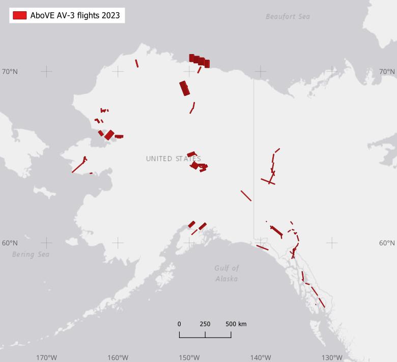
Figure 2. ABoVE flight paths of the AVIRIS-3 instrument during 2023 over Alaska, U.S., and the Yukon Territories, Canada..
The ABoVE project has used data from AVIRIS instruments to investigate ecological dynamics. For example, AVIRIS-NG data (Miller et al., 2024) enabled numerous studies during Phases 1 and 2 of the ABoVE project. Examples include assessing boreal forest fuel loading (Badola et al., 2022; Smith et al., 2021); methane emissions from wetlands (Elder et al., 2020; Elder et al., 2021; Baskaran et al., 2022), beaver hydraulic engineering (Clark et al., 2023), tundra fire burned areas (Yoseph et al., 2023), and tar sands oil production facilities (Borchardt et al., 2021). The ABoVE team has also made significant progress comparing vegetation classifications and traits derived from AVIRIS-NG compared to the values retrieved from centimeter-resolution uncrewed aerial vehicle (UAV) sensors (Nelson et al., 2022; Wang et al., 2023; Yang et al., 2023). Many additional studies and multi-sensor synthesis efforts are underway as part of Phase 3 activities.
Data Access
These data are available through the Oak Ridge National Laboratory (ORNL) Distributed Active Archive Center (DAAC).
ABoVE: AVIRIS-3 Imaging Spectroscopy for Alaska and Canada, 2023
Contact for Data Center Access Information:
- E-mail: uso@daac.ornl.gov
- Telephone: +1 (865) 241-3952
References
Badola, A., S.K. Panda, D.A. Roberts, C.F. Waigl, R.R. Jandt, and U.S. Bhatt. 2022. A novel method to simulate AVIRIS-NG hyperspectral image from Sentinel-2 image for improved vegetation/wildfire fuel mapping, boreal Alaska. International Journal of Applied Earth Observation and Geoinformation 112:102891. https://doi.org/10.1016/j.jag.2022.102891
Baskaran, L., C. Elder, A. A. Bloom, S. Ma, D. Thompson, and C.E. Miller. 2022. Geomorphological patterns of remotely sensed methane hot spots in the Mackenzie Delta, Canada. Environmental Research Letters 17:015009. https://doi.org/10.1088/1748-9326/ac41fb
Borchardt, J., K. Gerilowski, S. Krautwurst, H. Bovensmann, A.K. Thorpe, D.R. Thompson, C. Frankenberg, C.E. Miller, R.M. Duren, and J.P. Burrows. 2021. Detection and quantification of CH4 plumes using the WFM-DOAS retrieval on AVIRIS-NG hyperspectral data. Atmospheric Measurement Techniques 14:1267–1291. https://doi.org/10.5194/amt-14-1267-2021
Clark, J.A., K.D. Tape, L. Baskaran, C. Elder, C. Miller, K. Miner, J.A. O’Donnell, and B.M. Jones. 2023. Do beaver ponds increase methane emissions along Arctic tundra streams? Environmental Research Letters 18:075004. https://doi.org/10.1088/1748-9326/acde8e
Eckert, R., D.R. Thompson, A.M. Chlus, J.W. Chapman, M. Eastwood, M. Bernas, S. Geier, M. Helmlinger, D. Keymeulen, E. Liggett, S. Nadgauda, L.M. Rios, L.A. Shaw, W. Olson-Duvall, P.G. Brodrick, and R.O. Green. 2024. AVIRIS-3 L1B Calibrated Radiance, Facility Instrument Collection. ORNL Distributed Active Archive Center. https://doi.org/10.3334/ORNLDAAC/2356
Elder, C.D., D.R. Thompson, A.K. Thorpe, P. Hanke, K.M. Walter Anthony, and C.E. Miller. 2020. Airborne Mapping Reveals Emergent Power Law of Arctic Methane Emissions. Geophysical Research Letters 47:e2019GL085707. https://doi.org/10.1029/2019GL085707
Elder, C.D., D.R. Thompson, A.K. Thorpe, H.A. Chandanpurkar, P.J. Hanke, N. Hasson, S.R. James, B.J. Minsley, N.J. Pastick, D. Olefeldt, K.M. Walter Anthony, and C.E. Miller. 2021. Characterizing Methane Emission Hotspots From Thawing Permafrost. Global Biogeochemical Cycles 35:e2020GB006922. https://doi.org/10.1029/2020GB006922
Green, R.O., M.L. Eastwood, C.M. Sarture, T. G. Chrien, M. Aronsson, B.J. Chippendale, J.A. Faust, B.E. Pavri, C. J. Chovit, M. Solis, M.R. Olah, and O. Williams. 1998. Imaging spectroscopy and the Airborne Visible/Infrared Imaging Spectrometer (AVIRIS). Remote Sensing of Environment 65:227-248. https://doi.org/10.1016/S0034-4257(98)00064-9
Green, R.O., M.E. Schaepman, P. Mouroulis, S. Geier, L. Shaw, A. Hueini, M. Bernas, I. McKinley, C. Smith, R. Wehbe, M. Eastwood, Q. Vinckier, E. Liggett, S. Zandbergen, D. Thompson, P. Sullivan, C. Sarture, B. Van Gorp, and M. Helmlinger. 2022. Airborne Visible/Infrared Imaging Spectrometer 3 (AVIRIS-3). 2022 IEEE Aerospace Conference (AERO):1–10. https://doi.org/10.1109/AERO53065.2022.9843565
Miller, C.E., R.O. Green, D.R. Thompson, A.K. Thorpe, M. Eastwood, I.B. Mccubbin, W. Olson-Duvall, M. Bernas, C.M. Sarture, S. Nolte, L.M. Rios, M.A. Hernandez, B.D. Bue, and S.R. Lundeen. 2024. ABoVE: AVIRIS-NG Imaging Spectroscopy for Alaska, Canada, and Iceland, 2017-2022, V3. ORNL Distributed Active Archive Center. https://doi.org/10.3334/ORNLDAAC/2362
Nelson, P., D. Paradis, and W. Hantson. 2021. Scaling ground-based hyperspectral scans to AVIRIS next gen using UAV-based VNIR imaging spectroscopy for mapping arctic and boreal plants in Alaska. https://doi.org/10.1002/essoar.10508608.1
Smith, C.W., S.K. Panda, U.S. Bhatt, and F.J. Meyer. 2021. Improved Boreal Forest Wildfire Fuel Type Mapping in Interior Alaska Using AVIRIS-NG Hyperspectral Data. Remote Sensing 13:897. https://doi.org/10.3390/rs13050897
Thompson, D.R., P.G. Brodrick, R.O. Green, O. Kalashnikova, S. Lundeen, G. Okin , W. Olson-Duvall, and T. Painter. 2024. EMIT L2A Algorithm: Surface Reflectance and Scene Content Masks: Theoretical Basis. Jet Propulsion Laboratory, California Institute of Technology; Los Angeles, California. https://lpdaac.usgs.gov/documents/1571/EMITL2A_ATBD_v1.pdf
Thompson, D.R., V. Natraj, R.O. Green, M.C. Helmlinger, B.-C. Gao, and M.L. Eastwood. 2018. Optimal estimation for imaging spectrometer atmospheric correction. Remote Sensing of Environment 216:355–373. https://doi.org/10.1016/j.rse.2018.07.003
Thompson, D.R., K.N. Babu, A.J. Braverman, M.L. Eastwood, R.O. Green, J.M. Hobbs, J.B. Jewell, B. Kindel, S. Massie, M. Mishra, A. Mathur, V. Natraj, P.A. Townsend, F.C. Seidel, and M.J. Turmon. 2019. Optimal estimation of spectral surface reflectance in challenging atmospheres. Remote Sensing of Environment 232:111258. https://doi.org/10.1016/j.rse.2019.111258
Thompson, D.R., A. Braverman, P.G. Brodrick, A. Candela, N. Carmon, R.N. Clark, D. Connelly, R.O. Green, R.F. Kokaly, L. Li, N. Mahowald, R.L. Miller, G.S. Okin, T.H. Painter, G.A. Swayze, M. Turmon, J. Susilouto, and D.S. Wettergreen. 2020. Quantifying uncertainty for remote spectroscopy of surface composition. Remote Sensing of Environment 247:111898. https://doi.org/10.1016/j.rse.2020.111898
Wang, C., T.M. Pavelsky, E.D. Kyzivat, F. Garcia-Tigreros, E. Podest, F. Yao, X. Yang, S. Zhang, C. Song, T. Langhorst, W. Dolan, M.R. Kurek, M.E. Harlan, L.C. Smith, D.E. Butman, R.G. M. Spencer, C.J. Gleason, K.P. Wickland, R.G. Striegl, and D.L. Peters. 2023. Quantification of wetland vegetation communities features with airborne AVIRIS-NG, UAVSAR, and UAV LiDAR data in Peace-Athabasca Delta. Remote Sensing of Environment 294:113646. https://doi.org/10.1016/j.rse.2023.113646
Yang, D., B.D. Morrison, W. Hanston, A. McMahon, L. Baskaran, D.J. Hayes, C.E. Miller, and S.P. Serbin. 2023. Integrating very-high-resolution UAS data and airborne imaging spectroscopy to map the fractional composition of Arctic plant functional types in Western Alaska. Remote Sensing of Environment 286:113430. https://doi.org/10.1016/j.rse.2022.113430
Yoseph, E., E. Hoy, C.D. Elder, S.M. Ludwig, D.R. Thompson, and C.E. Miller. 2023. Tundra fire increases the likelihood of methane hotspot formation in the Yukon–Kuskokwim Delta, Alaska, USA. Environmental Research Letters 18:104042. https://doi.org/10.1088/1748-9326/acf50b